Wednesday, December 14, 2005

Happy Holidays


It's that time of the year hopefully for most of you.
Its what we call Builders Break. All construction comes to a grinding halt from the 15th December to the 10th January, and every one in the built industry takes a much needed break!!

Today is our last day of work for the year. I am off for a 4 week vacation. Sun, sandy beaches and ice cold beer await.

As I am off together with wife and the kids too some quiet, remote, rural place along our sunny coastline, internet connectivity is non existant. So I will only start blogging again in mid January.


I do wish you all Happy Holidays and a great New Years!!!!
Cheers

Wednesday, November 30, 2005

Horizontal View Titles

When you alter the view rotation on a sheet to 90deg Clockwise or alternatively 90deg counterclockwise, inevitably the view title rotates with it.
By creating two new view title families you can eliminate the problem.

1. Open the existing view title family or alternatively your customized view title family.
2. Select what you need and first rotate it 90deg.
3. Reposition if necessary
4. Save this as the 90deg file.


5. Create another view title in the same manner, but this time rotate the necessary text -90deg.
Before doing so select the text that is going to be rotated and uncheck the “Keep Readable” parameter.
6. Save this as the -90deg file.


7. Now load these new families into your project.
8. Go to a sheet view and select a view that is rotated.
9. Select the properties of the view title, then Edit/New. Now select Duplicate.
10. Type in a new name and OK
11. In the “Title” Parameter change the value to your new family 90deg or -90deg depending on the rotation of the view
12. Apply, OK and you should have a 0 deg or straight view title.


Friday, November 25, 2005

Revit Gaining Momentum!

Not only is Revit gaining momentum in the Architectural Industry but in blogs as well.
Bruce Gow, (or Beegee to most, from ZOOG days and now AUGI), has started his own….. Revitalize. I am sure with all his experience and knowledge, will add yet another informative Blog on Revit.
Be sure to check it out.

Tuesday, November 15, 2005

Current Project

here are some images from a current project.


Perspective Views


Joinery/Casework Details and schedules


Detail Sections


Handrail Details


Aluminium Shopfront/window schedule


This is one of the smaller hospitals I am involved with. Three Stories, plus basement parking. This was a new 10 000 sqm addition to an existing 20 000sqm hospital. We built the entire existing building in Revit, phased it and added the new work. The above images reflect the level of detail and documentation we go too, all done in Revit!!
No external or 3rd party apps used to achieve the end result or construction documentation. No Lines are used, detail or otherwise. The whole project consists of families. The less rubbish we put in the smaller the file size.

We decided to totally Revitize this project. No DWG links, no DWG whatsoever!!! No unnecessary “BLOAT” added to the project. The result was extremely surprising. The benefits and results found in doing a complete Revit project are astounding. If you want to keep it simple, and keep it small, the solution is in building and loading families!

The building is probably 60% built. I will post photos as we go.

Reference goodies continued

Reference Lines
Reference lines were introduced from Release 7 of Revit. Its purpose being, to set up angle parameters. Reference lines together with an angular dimension parameter, control any geometry attached to the angular reference. For example, the web of a truss. Reference lines also provide two planes, one parallel to the plane the other perpendicular to the reference plane. Although reference lines cannot be named, one can use these two planes to create a Work Plane from.


After selecting the Work Plane tool, select “Pick a plane”, in the Work Plane dialogue box. By using the Tab Key, filter through the selection of the two which you would like to set as current.

Monday, November 14, 2005

Understanding Reference Planes and Work Planes

When I asked student’s “What was the most difficult part of Revit to understand” the answer nine out of ten was “Reference Planes vs Work Planes”. To further continue building families we first need to understand a bit of Revit’s terminologies, i.e. Reference Planes, Reference Lines and Work Planes.

Reference Planes, and the Family Editor.
In the Family Editor, “Reference Planes” are the KEY to successful families! Reference Planes have no end. Reference planes are in effect, “Construction lines” or guide lines to aid in your parametric design. Once dimensions are added between the Reference planes, unique parameters such as, Height, Width or Length can be assigned to the dimensions. These parameters now allow you to “Stretch Your Model”. There is no stretch command in Revit, and this becomes your means of stretching, by altering the parameter. Now a Parametric Model.

Before any geometry is built in a family it is advisable to, first set out the Reference planes then the dimensions and lastly the solid geometry. Any geometry built on reference planes are automatically locked to their parameters.

Most, if not all of the family templates (*.rft) which Revit provides, have some sort of “startup kit”, ready to use, and are laid out as a guide, for you to further improve on the parameters. Every one of them have a cross of reference planes in the plan view, the intersection of which, defines the origin or “insertion point”. This Origin can be altered by simply changing the properties of the reference plane.

Reference Planes vs. Work planes.

In the Family Editor more than in the project, you will need to deal with both Reference planes as well as Work Planes.
This is where it gets most people confused.
Most views in Revit have an automatic Work Plane. Remember you are not only constructing in the X and Y axis but as well as the Z.

Simple enough?
It is actually. Once a reference plane is named it becomes a Work Plane. To name a Reference plane, simply add a unique name in the Name Field under its properties.

Revit will by default automatically assign a Work Plane for the specific view you are in. For example in the level 1 floor plan, automatically the Work Plane is at Level 1. When using the Family editor all plan views are set to Reference Level. By default the Work Plane is automatically the Ref. Level. At any point you can define which plane to work on and check if it’s the correct one by firstly using the Work Plane Icon (1) and setting the correct work plane.


Secondly, selecting the Work Plane Visibility Icon (2), will give a clear indication as to which Work Plane is set as current.


Wednesday, November 09, 2005

"Revitize" Legacy Data

All your life work and collection of suitable CAD symbols that make your documents unique need not be wasted. “How do we Transfer our Legacy Data into Revit” Is a question I had in every training course I have given.

Not all Revit content or Families, have to be fully Parametric! We took the stand or view, that certain components unique to our block library need not be. For example, all the Plumbing fixtures such as WC’s, Urinals, Basins, Sinks and Baths, were taken straight from the Manufactures DWG library. We Load and place the exact component as per the manufacturers catalogue. Most Components that we have accumulated over the years have got plan, side and front views, and from these we build up multi-view components.

Before starting with importing the DWG’s it is advisable to clean them up and ensure that all lines in the DWG are on layer Zero. That way there is less to clean up in Revit, as all layer properties are transferred with the Dwg. This creates a lot of extra subcategories in the Object Styles that complicate matters when cleaning up the Revit family.

The key to transforming from Dwg to Revit Family, is to make it Revit or to “Revitize” it. By this I mean, perform a “Full Explode” of the Dwg, and change Dwg lines to Revit lines, plus get rid of any hint of Dwg in the file. The cleaner it is, the more Revit like it becomes.

Alternatively you can trace over the Dwg using Revit’s tools and delete the Dwg afterwards.
The simple trick is, is not to leave any remains of the Dwg behind. This just adds “BULK” to the Project. By doing a quick check on the Subcategories in the Object Styles, one can immediately tell if you didn’t clean your DWG to start with.You can delete the “Layers” from the Object Styles and any lines that were on those layers will change to the Default Family Category.

Do not create a Family by using the imported symbol and leaving it there. Revitize it and get rid of the DWG! It will come back and bite you on the ....at a later stage.

The objective here is to eventually move away from dwg entirely. I have been dwg free for a year now!!!
It’s all Revit or Bust!


Tuesday, November 01, 2005

RSS Feed Added

Just added RSS Feed with feedburner. Click on the Feedburner icon in the sidebar for more info!

Thursday, October 27, 2005

Revit Family Editor

Here in lies the key to completing successful projects using Autodesk’s Revit. Without the ability to create or edit your own families, the whole Revit migration cause is lost. After purchasing the software, you generally get fixed into a training course, with hopefully a reputable Autodesk Accredited Training Centre, who teaches fundamentals for 5 days. There after you are left to your own devices on mastering Revit. Revit families can and will “eat you up and spit you out”

Without mastering the “Family Editor” which generally doesn’t feature during “Fundamentals”, you will be even more lost. Every Project is unique, therefore, the need to create unique content to complete successful CD’s is even greater. It’s the complexity to which you create and manage these families, that makes the whole experience unique in it’s own. Prior to R 8.0 the Autodesk Revit Family Editor was very detached from the program. With the new added “Edit Family” Button on the “Options Bar” editing families is now made so much easier

The whole concept behind families is that of building a library, much like blocks. But instead of 3-4 different baths, at different lengths, we can now create 1 bath to suite all. I like to think of it as “one size fits all”…….Parametric. Although Revit does allow you to create families with in the project namely “in Place Families”, I strongly advise against it. Purely, for the reason of, RE-USE. Create the family once and RE_USE over and over. Create with in the project and it becomes project specific, with no way of saving out as yet!

We are currently experiencing the benefits to our extensive library which we started building in 2002, and are still adding to it. It is now a case of just populating the database with components and printing schedules. All the information is stored with in the family needed to complete the relevant schedules of data.

I have recently covered the standard UI for Revit. Now we tackle the “Family Editor” UI.
Upon creating a new Family, Revit first of all asks to which supplied template would you like to categorize the new family. These templates are all individually laid out with all the necessary start up kits pertaining to that specific model/category. Choosing the correct family template is crucial to the start of a new life. Having said that, don’t be concerned though if you have created the family under the incorrect category, it can be changed and this will be covered at a later stage.

You will notice first of all that the “Design Bar” looses all it’s tools and is replaced by the “Family Editor Design Bar”. In it you will find all the necessary tools to create your new Family. The tools available differ from template to template.


The biggest issue we had to deal with, after converting to Revit, is of course, all the cad symbols, “blocks” we had collected over the last 12 years of Autocad – “Legacy Data”. Especially, the symbols provided by manufactures that we used to filling our drawings with. We place the block that actually represents the plan representation of the fixture we intend to specify (this also defines a unique look to our drawings). For example, we have over 30 basins/vanity’s to depict the correct specification. So to keep with-in our office standards, we had to transfer all this legacy data. (fortunately we had students that I trained up to do this for us). In the Following exercise we will be covering exactly that.

How to, “REVITIZE” your current library from "Legacy Data".

Alternatively you pay money for a Revit implementation specialist to come and help.

Wednesday, October 26, 2005

Revit Formulae

So... I will just jump straight in here.
Many of the formulae conditions can be replicated re-used etc.
The Help files are most useful when starting out with formulae in Revit.
Also hunt around in www.augi.com

Here is some "help file" extrapulation....


You can enter formulas for calculating parameter values. Formulas may include numerical constants and other parameter names. For example, the family could have two parameters named Length and Width. The value for Width might be calculated with the formula Length/2.

Formulas are case sensitive. If the parameter names have initial capitals, you must enter them in the formula with capitals. For example, the parameter name is Width. You type width * 2 in the formula. This is ambiguous to Revit Building, and it does not accept the formula.

Formulas support the following arithmetic operations: addition, subtraction, multiplication, division, exponentiation, logarithms, and square roots. Formulas also support the following trigonometric functions: sine, cosine, tangent, arcsine, arccosine, and arctangent.

For numerical values in formulas, you can enter integers, decimals, or fractional values.

Formulas are available for instance parameter values in the project. You must begin the formula with an equal sign. For example, as you sketch a wall, you can enter a formula for the temporary dimension for the wall. Click , and you can enter formulas for numerical properties of the wall, such as Unconnected Height and Base Offset.

TIP: Keep your units consistent. Do not mix units in your formulas. You can use constants with no units assigned to them.

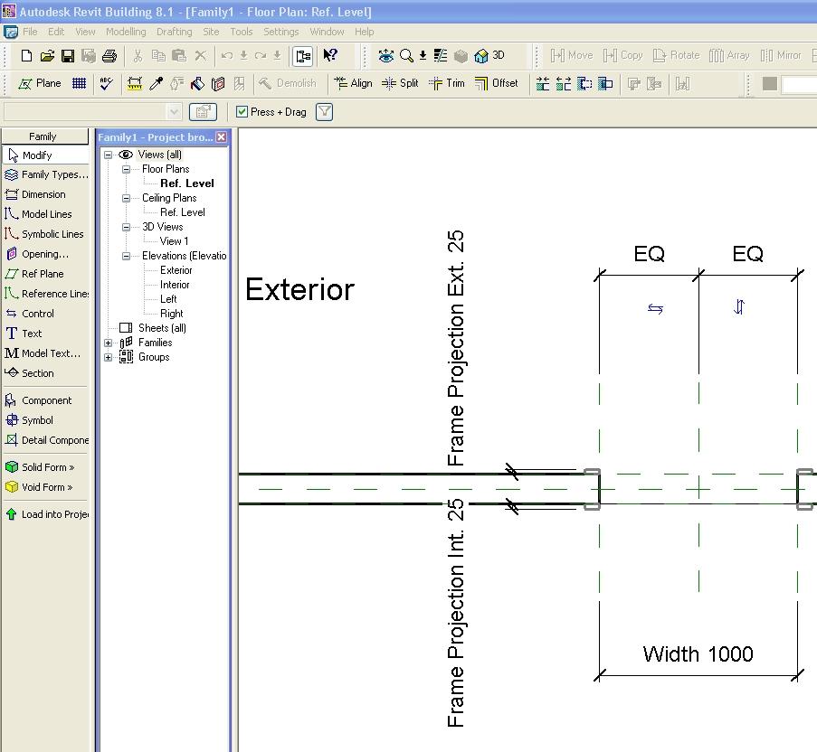
Length = Height + Width + sqrt(Height*Width)
Length = Wall 1 (11000mm)+ Wall 2 (15000mm)
Area = Length (500mm) * Width (300mm)
Volume = Length (500mm) * Width (300mm) * Height (800 mm)
Width = 100m * cos(angle)
x = 2*abs(a) + abs(b/2)
Create the family geometry.
Create and label dimensions to the geometry. See Labeling Dimensions. Do not select the Instance Parameter option. In the Family Editor, formulas are available for type parameters only.
Click Family Types from the Design Bar.
In the Formula column next to the appropriate parameter, type the formula for the parameter. Notice that the formula begins with an equal sign (=).

Formulas can comprise conditional statements. You enter conditional statements in the Formula box for a numerical parameter.

A conditional statement uses this structure:

IF (, , )

This means that values are entered for the parameter, depending on whether the condition is satisfied (true) or not satisfied (false). If the condition is true, return the true value. If the condition is false, return the false value.

Conditions can use numeric values, numeric parameter names, or Yes/No parameters. You can use the following comparisons in a condition: <, >, =. You can also use Boolean operators with a conditional statement: AND, OR, NOT. Currently, <= and >= are not implemented. To express such a comparison, you can use a logical NOT. For example, a<=b can be entered as NOT(a>b).

The following are some sample formulas that use conditional statements.

Simple IF: =IF (Length < 3000mm, 200mm, 300mm)

IF with logical AND: =IF ( AND (x = 1 , y = 2), 8 , 3 )

IF with logical OR: =IF ( OR ( A = 1 , B = 3 ) , 8 , 3 )

IF with Yes/No condition: =IF (Long, 50, 60) where Long is a Yes/No parameter defined as Long = Length > 40

Embedded IF statements: =IF ( Length < 35' , 2' 6" , IF ( Length < 45' , 3' , IF ( Length < 55' , 5' , 8' ) ) )

The following are valid formula abbreviations.

Addition— +
Subtraction— -
Multiplication—*
Division—/
Exponentiation—^: x^y, x raised to the power of y
Logarithm—log
Square root—sqrt: sqrt(16)
Sine—sin
Cosine—cos
Tangent—tan
Arcsine—asin
Arccosine—acos
Arctangent—atan
e raised to an x power—exp
Absolute Value—abs

Tuesday, October 25, 2005

Collaboration

My good friend and Reviteer has joined me in contributing to this site.
Welcome Mike!!

Friday, October 21, 2005

Getting to know Autodesk Revit's User Interface

The following image outlines the basic user interface for Autodesk Revit.


Know your "Options Bar".
Autodesk Revit’s User Interface is by far the easiest I’ve come across in terms of Architectural software.
Behind the Standard UI is in fact a “Hidden UI”. It exists in the “Options Tool Bar”
The biggest piece of advice I could give with regards to the User Interface is, constantly monitor the “Options Bar”. With almost every command the “Options Bar” changes it’s state. Get to Know it!!


Know your "Properties".

Together with the “Options Bar”, the “Properties” dialogue box, is by far the most complicated parts of the UI.


There are two parts to the dialogue box. Namely :
1. Instance parameters: Parameters that effect only the selected object and no other.(found in the first part of the diag.)
2. Type Parameters: Parameters which change every object in the project. (second Part of the Diag.)
With every element you select the properties and parameters are different. There are many standard Parameters that Revit automatically assigns, especially in System Families*. Since Revit 7.0 the “Properties Dialogue” took on a much needed overhaul. Parameters are now categorized, and easdier to find. Still, when it comes to custom families anyone can put anything anywhere. So, Get to know what to look for!

Due to the fact Revit is a Parametric Modeler, you more often than not change the parameter to change the object/model. There's no "Stretch" command. However since release 8.0. Instance length parameters now have "handles" grips, that one can use to pull or push to change a size.
Get to know your parameters.

*System Families= Walls , Floors, Roofs, Ramps, Stairs, Railings, Ceilings.

Wednesday, October 12, 2005

Accomplishments?

Before we get started on the “Best Practices for the Family Editor” you will probably wonder, as to what makes us qualified to give instruction.

Together with an Autodesk Reseller, I started researching Revit from Revit 4.0.
Autodesk then added Revit to their “stable”.
Approximately 8 months later, we then selected a few reputable architectural firms, to run pilot sites of Revit 5.0. Only three took the bait, out of the selected ten. I then took on the task of training the select few. Afterwards, helping them in implementing Revit in their offices, with the sole intention, of not letting them touch, any cad software other than Revit for the next three months.

Over the next two years Revit took off, exceeding all expectations. I trained an excess of 120 individuals, as well as, sat through their pain in trying to implement.In that time we also took on the task of building all the local standards, as well as local manufacturer’s components, as families. Together we built a library of over 1.2GB. This gets sold as part of a Revit package, by the reseller.

Accomplishments continued....

Over the next year I continued to implement Revit at A3 Architects-Inc, who happened to be my first pilot site in South Africa. Combined, we have rolled out at least 8 projects, done only using Revit.
Three of which are large Hospitals, the largest, a 27 000sqm 200mb complete database file.
The smallest hospital of the three, benefited largely, on all the families we had already set up, and standardized. Thereby, making it the quickest set of “Construction Documentation” rolled out in this office. All three are currently under way with construction.

We took time in establishing an office standard that the three of us (the Office Family Creators) would stick to. Constantly having “Family Planning” meetings (I sound like a psychologist), which would determine the best methods needed, to make the next set of families benefit us the most, in terms of the look and the data attached.

However, not always did we take the best or most efficient path, and would have to “Reverse Engineer”. But the outcome of all our research is what should benefit you, in creating a successful and complete Family and Library

Monday, October 10, 2005

New To Blogging

I have found Blogs! I find this concept quite fascinating, and thought,I too would start something in which I can share the knowledge.

I am a Revit Implementation Specialist in South Africa. I started on Revit even prior to Autodesk’s buy out. Revit 4.0.
I specialize in Large projects and the efficiency in running them using Revit. Through my experience I have become somewhat the Family Specialist, for here-in lies the secret to successful projects in Revit.

After helping various users on AUGI to sort there families out, someone posted "Why dont you write a book".
Thru' this Blog I will attempt to share our findings in family creation inside Revit. Starting where we started, with the simple stuff thru' to the advanced families we are busy creating today.

After purchasing Revit from a reseller you probably attended a course of some sorts, and then you are left to your own device to try take on the daunting task of a complete project using only Revit to complete your CD's.

Well I hope to shead some light on this very powerfull tool that lies within Revit. The Family Editor.