Friday, February 23, 2007

My Job here is still not done?

It wasn’t a month ago that I put a report together for the top management, based on the progress of Revit Users I have been implementing at a medium to large practice here in SA. It has been 6 months since I had started and I sat back with my broad shoulders almost expanding through the width of the door, patted myself on the back and thought “job well done”.

Then…..with some extra workload in the firm I took on a project for them. At stages I could see a questioning expressions creeping in from management. I had no idea what I had got myself into, or what was about to unravel from it all.

Where did it all go wrong! I look back at it now and it’s all quite simple.

The implementation goal was to convert an office of autocad users to using Revit. That’s how simple the planning was. It seemed quite complicated at the time. We drew up all sorts of schedules related to planning, converting, stages, fundamentals, families etc. and based this all on time lines, in other words what we though was a comprehensive implementation plan.

We then set the plan in motion. We screened the users, reviewed the projects, set up comprehensive templates, built the standards and the families to go with that, set about creating teams and created extensive training schedules to coincide with the team workflow and project workflow.

All this had to fall in line with the amount of projects in hand, as well as the expected documentation process or workflow we had to adhere to which had been fine tuned and perfected over the years of working in ACAD.

Well we achieved all that with sticking to the projects time lines!

So you ask what’s the problem then?

Well, while doing the project I was assigned, I found that I was exceeding all expectations of the project time constraints set by the project manager and project architect. As one does with efficient Revit use I was constantly waiting on the rest of the project consultants (all still using CAD) for information, and to catch up…….then finally get it back and whack out the next batch of changes plus CD’s to go with it. (Yawn all in a few hours work! Jeez this program rocks!!)

The poo hit the fan about here! When asked for some window, door and sanitary schedules, click and two or so hours later…. printed. see example


It took one dude here, 5 days to do just a door schedule, and he is not the only one in the office.

I have now been called in to review and access the individual’s actual Revit knowledge, (where did I put that Revit test I had from…..?) because, top management is now interested to see, is it that the individual himself is just slow, is it Revit(which we know it isn’t), is it the combination, is it , is it, is it.

The BIG question has now been raised on the productivity of the team using Revit.

So I find myself in quite the position (sticky mess). I now have to do a report based on the individual’s abilities then we throw this all into the pot and ask the obvious questions.

Is it, the implementation plan that is flawed…. maybe.

Is it the individual. (in that case, how do we get rid of the baggage?)

Is it, just human to do what is expected.

Is it, that which the processes and workflow standards of years, are so set and are difficult to change.

I can tell you what my findings will probably be.

The fact of the matter is, people took a week using CAD to do a comprehensive door schedule for example, why should he/she do it now in a day or even a few hours at that.

Yes, I can do things much quicker using Revit but it still takes so long to build, so why should I document it quicker. And if your construction labor force is anything like ours, mistakes creep in, and we need to be hands on, throughout the duration of the project, constantly updating and amending the project, so as to achieve the “as builts” set for submission, by the time of completion. By this, one assumes that the productivity of the software is questionable.

People often complain of having worked on a project for 18 months now, and are simple frustrated and bored. I know I would much rather do 6 different projects a year than one.

In the vision of things, can we get to the point in the near future whereby we complete all CD’s before site hand over? That way we will be able to quickly move onto the next and the next.

I feel, this can only be achieved by changing the mind set of the user and ultimately using BIM efficiently.

So, onwards to my next 12 month task. Review the implementation plan and include "How to work efficiently using Revit?"

Friday, February 09, 2007

Families for the masses?

On a number of occasions, have I had users complain about families, the lack of content and the ability to build custom stuff.
The ability to build your own comes with lots of understanding and tons of practice.

By lack of content, I simply mean that for example a client wants a window that is fixed on one side and double top hung on the other. Simple enough.
Far too many users try re-invent the wheel, and build these things from scratch, why on earth..... when you already have the window designs in your library. All you have to do is piece them together.... it's called nesting.

Here is a simple exercise to learn how.

1. Start a new family using the Window.rft as the template of choice.

2. Goto the 3D view and select the opening cut in the wall and delete it.(if this does get a little tricky use the TAB key to cycle through the selection while the mouse is resting on the opening cut.)

3. Goto the Floor Plans; Ref Level view.( double click on ref level in the project browser.... dopey...NO! not the one under Ceiling Plans....Floor Plans).

4. File; Load from Library; Load Family! in your windows directory in your library we need to select two windows. Highlight the Double Hung.rfa then Ctrl key to add the Fixed.rfa, now click open. Depending on whether you have imperial or metric libraries, the prefix to the files will differ, ie. M_Double... or I_Double.......


5.Set up a vertical Ref Plan around 600mm from the right side's Ref plan back towards the center. this is going to control the double hung's width. What ever is remaining is going to become our remainder width for the fixed window.


6. Dimension that width, select the dimension and add a label to it.
(right click, Edit Label select Add Parameter, or select the label function on the Options tool bar... slab bang in the top middle of your screen and select Add Parameter from the drop down list.
Name the label Double Hung Width, and group it under Dimensions


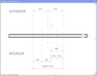
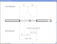
7. For the nested windows to work properly they need centerlines to align and grow from. Create Ref planes and EQ dimension as per the fig.


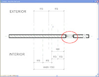
8. Select the component tool (Design bar on the left), in the type select, then choose the smaller double hung window 406 x 1200mm from the list and place it anywhere along the wall.


9. Align the window in plan to the center line Ref Plane we created and lock.


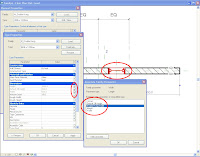
10. Now associate the windows parameters with the new families parameters. ie select the window and goto its properties, Select edit(top right of dia) select the little box along the end of the height parameter and equal it to height. Do the same for Default Cill Height. Make the width = to the new Double Hung Width we created.


11. We now need to set up a remainder width parameter to associate the fixed window width too.

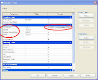
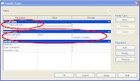
12. Select Family Types in the Design bar. Click Add Paramater, name the parameter Remainder, group it under Dimensions and make it a length Type Parameter.

13. Add the following formula to the Remainder parameter... Width - Double Hung Width. Parameters are case sensitve.


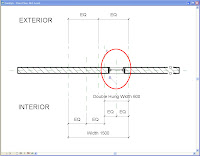
14. Now Place the Fixed 406 x 1220mm window along the wall. Align and lock the window to the second center ref plane we created. Follow the same steps as in step 10 except for the width. Associate this windows width to the Remainder parameter.


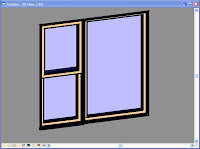
Right, simple hey! Your window should look like this.

15. Goto family types, "stretch your family" test all the parameters to see if it all works. (If it doesn't.... take this number down, 555 6352 -- it's the care bears hotline.)


Now set up new family types, load into projects and start using.

Nested families rock! In previous post I spoke of family starter kits, well... this is taking it to the next level. We have soooo many families and mostly combine all the parts to make one. Enjoy

Thursday, February 01, 2007

Text value Line Styles

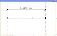
Here is a quick tutorial on how to create line styles in Revit whereby you can change the text values. We use this for lines like Fence, Hot water, Cold water etc.


1. Start a new family - annotation symbol - generic annotation.
2. Delete the Red text warning.

3. Add a Label. Click mouse pointer at the intersection of ref Planes.


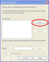
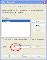
4. In the Select Parameter Dialogue box click Add.


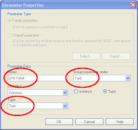
5. In the Parameter Properties Dia Name Feild : Line Text Value.
6. Leave it as a text parameter, and group it under Text.


7. In the Select Parameter Dialogue box type a value of f ( at the bottom.)
8. Save this file.


9. Start a new family using the Detail component line based template.

10. Alt+Tab back to the symbol family(or pick in the window pull down)

11. Load the symbol into the detail line base new family.


12. Using the symbol tool place the symbol near the 1st end point of the line(on the left hand side.


13. Using the align tool align and lock the symbol to the reference planes vertically as well as horizontally.

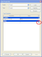
14. Sellect the symbol and cross associate the "line text Value" parameter through to the new family. ( hit the little inconspicious square box at the end of the paramters field, this will take you to the add parameter dialogue box. Ie follow steps 4-7 again)


15. select the symbol, now use array tool with the set the amount to 4 and tick last option and array the symol from the left to the right side.


16. Align and lock the last symbol as per step 13.

17. One could add an array parameter here or better yet, add an array formula that divides the line length by centers set up for the text.


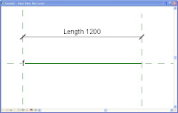
18. Lastly draw a line style of your choice fom left to right.

19 Load into your project and using the detail component tool, set up all your fences and so on.

20. Edit duplicate change the name, change the text value (hot water) and off you go doing your water reticulation CD's

Pleasure.......glad I could help